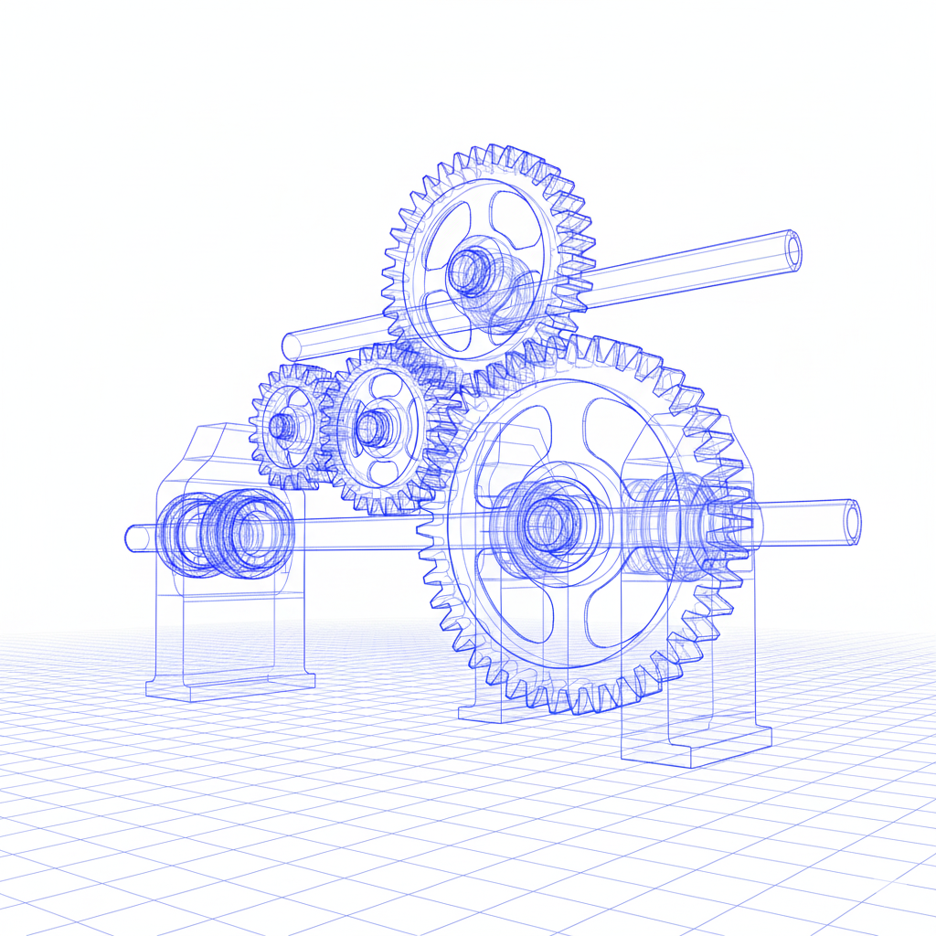
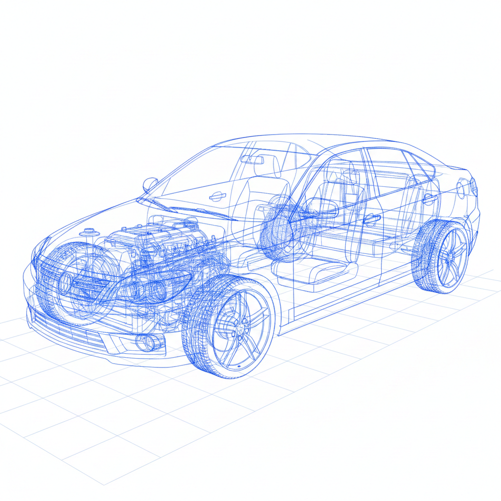
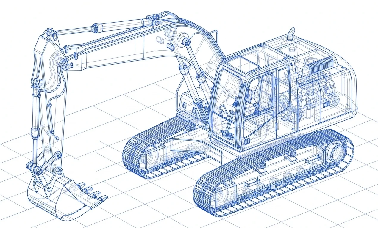
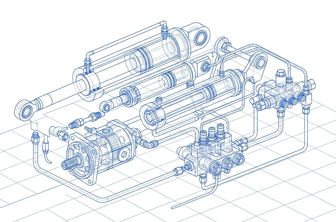




Gears are essential mechanical components used to transmit motion and torque between rotating shafts or convert rotational motion into linear movement. They play an important role in automotive transmissions, industrial machinery, agricultural equipment, construction equipment, robotics, and power transmission systems. Different gear designs serve different purposes depending on the required speed, load, direction of motion, operating conditions, and available space.
Understanding the types of gears helps engineers, equipment manufacturers, and procurement professionals identify suitable components for their applications. Common designs include spur gears, helical gears, bevel gears, worm gears, planetary gears, rack and pinion systems, and herringbone gears. Each has distinct characteristics, advantages, and limitations.
This guide explains the different types of gears, how they work, where they are used, and which factors to consider when selecting a suitable gear for an industrial or automotive application.
What Are the Different Types of Gears?
Gears are toothed mechanical elements that transmit movement and power through meshing teeth. Their geometry determines how they interact, the shaft arrangement they support, and their operating characteristics.
The main types of gears include:
- Spur gears: Straight teeth used primarily between parallel shafts.
- Helical gears: Angled teeth that engage progressively and are commonly used between parallel shafts.
- Bevel gears: Conical gears used to transmit motion between intersecting shafts.
- Worm gears: A worm and wheel arrangement commonly used for substantial speed reduction between non-parallel, non-intersecting shafts.
- Planetary gears: A gear system consisting of sun, planet, and ring gears with a carrier.
- Rack and pinion gears: A circular gear and a straight toothed rack that convert rotational movement into linear movement.
- Herringbone gears: Double-helical gears with opposing tooth directions.
- Internal gears: Gears with teeth cut on the inside of a cylindrical ring.
The appropriate design depends on the application, required transmission ratio, load, efficiency, available space, lubrication, and manufacturing requirements.
1. Spur Gears: Simple and Widely Used Gear Types
Spur gears have straight teeth parallel to the gear shaft. They typically transmit motion between parallel shafts and are among the most straightforward gear designs to understand and manufacture.
When two spur gears mesh, their teeth engage to transfer rotational motion from one shaft to another. The relationship between the number of teeth determines the speed ratio, while the gear dimensions and material influence load capacity and durability.
Advantages of Spur Gears
- Simple and compact design
- High mechanical efficiency when properly designed and lubricated
- Straightforward inspection and maintenance
- Suitable for a wide range of industrial mechanisms
- Relatively uncomplicated manufacturing compared with many specialized gear forms
Applications of Spur Gears
Spur gears are used in industrial machinery, gear trains, suitable automotive mechanisms, machine tools, and equipment requiring straightforward power transmission between parallel shafts.
When Should You Choose Spur Gears?
Spur gears are worth considering when the shaft arrangement is parallel, the design requires a straightforward transmission system, and operating noise is manageable. At higher speeds or under demanding noise requirements, other gear designs may be more suitable.
2. Helical Gears: Smooth Tooth Engagement for Industrial Drives
Helical gears have teeth cut at an angle to the gear axis. Unlike spur gears, their teeth engage progressively, which can produce smoother and quieter operation under suitable conditions.
They are commonly used in industrial gearboxes, automotive transmissions, conveyors, and machinery that requires reliable power transmission.
Advantages of Helical Gears
- Progressive tooth engagement
- Smooth operation under appropriate operating conditions
- Potential for higher load capacity than a comparable spur gear arrangement, depending on design
- Suitable for many industrial transmission applications
- Often preferred where operating noise and vibration need to be controlled
Applications of Helical Gears
Helical gears are commonly found in industrial gearboxes, material-handling systems, automotive transmissions, compressors, and other equipment where smooth power transmission is important.
What Should You Consider?
The angled teeth create axial thrust, which must be accommodated by the shaft, bearings, and housing. Helical gears can also introduce additional sliding contact and manufacturing complexity. Proper design, lubrication, alignment, and bearing selection are therefore important..
3. Bevel Gears: Power Transmission Between Intersecting Shafts
Bevel gears have a conical form and are designed to transmit motion between intersecting shafts. Their shaft angle is often 90 degrees, although other configurations are possible.
They are useful when a mechanical system needs to change the direction of power transmission within a compact arrangement.
Main Types of Bevel Gears
Straight bevel gears: These have straight teeth arranged along the conical surface. They are used in suitable applications where their geometry and operating characteristics meet the design requirements.
Spiral bevel gears: These have curved teeth that engage progressively. They are often selected where smoother engagement and higher-speed performance are important.
Miter gears: These are a bevel gear pair with equal tooth counts, generally used to transmit motion between shafts at a 1:1 ratio.
Advantages of Bevel Gears
- Change the direction of power transmission
- Support intersecting-shaft arrangements
- Available in different tooth configurations for varied applications
- Can be designed for demanding mechanical power transmission systems
Applications of Bevel Gears
Bevel gears are used in differential mechanisms, industrial machinery, selected automotive systems, agricultural equipment, and machinery where intersecting shafts are required.
How Do You Select a Bevel Gear?
Consider the shaft angle, transmission ratio, load, operating speed, mounting accuracy, lubrication, and required tooth quality. Straight and spiral bevel gears are not interchangeable in every application; their selection should be based on the mechanical design and performance requirements.
4. Worm Gears: Compact Speed Reduction
Worm gears consist of a screw-like component called a worm and a mating gear known as a worm wheel. The arrangement transfers motion between shafts that are generally non-parallel and non-intersecting, often at a right angle.
Worm gear systems are commonly used where substantial speed reduction is needed within a compact arrangement.
Advantages of Worm Gears
- Can provide substantial speed reduction in a single stage
- Compact transmission arrangement for suitable applications
- Smooth motion under appropriate operating conditions
- Useful where a right-angle drive configuration is required
Applications of Worm Gears
Worm gears are used in selected conveyors, lifting mechanisms, positioning systems, machine tools, and industrial drive equipment.
What Are the Limitations of Worm Gears?
Sliding contact between the worm and wheel can generate heat and reduce efficiency compared with some other gear arrangements. Material pairing, lubrication, operating speed, and thermal management are important design considerations.
A worm gear arrangement should not automatically be assumed to be self-locking. Its resistance to back-driving depends on the design and operating conditions.
5. Planetary Gears: Compact and Versatile Gear Systems
Planetary gears, also called epicyclic gears, use multiple gears arranged around a central gear. A typical system contains a sun gear, planet gears, a planet carrier, and a ring gear with internal teeth.
Depending on which component is held, driven, or used as the output, a planetary gear system can provide different speed ratios and torque characteristics.
Main Components of a Planetary Gear System
- Sun gear: The central gear that meshes with the planet gears.
- Planet gears: Gears that rotate around the sun gear while being carried by the carrier.
- Planet carrier: Supports the planet gears and rotates around the central axis.
- Ring gear: The outer gear with internal teeth that meshes with the planet gears.
Advantages of Planetary Gears
- Compact design for suitable transmission ratios
- Multiple gear meshes can share the transmitted load
- Flexible ratio arrangements
- Coaxial input and output configurations are possible
- Suitable for demanding transmission applications when properly designed
Applications of Planetary Gears
Planetary gear systems are used in automotive automatic transmissions, industrial gearboxes, selected electric drive systems, heavy machinery, and applications requiring compact torque transmission.
When Are Planetary Gears Suitable?
They are worth considering when packaging space, transmission ratio, torque capacity, and coaxial shaft arrangements are important. Their design and assembly can be more complex than simpler gear arrangements, so manufacturing accuracy and system-level engineering are critical.
6. Rack and Pinion Gears: Converting Rotation into Linear Motion
A rack and pinion mechanism consists of a circular gear, called the pinion, meshing with a straight toothed component called the rack. As the pinion rotates, the rack moves in a straight line.
Unlike gear pairs that transmit rotation between shafts, a rack and pinion system converts rotary motion into linear motion or vice versa.
Advantages of Rack and Pinion Systems
- Direct conversion between rotary and linear movement
- Relatively simple operating principle
- Suitable for controlled linear positioning
- Flexible design options for different travel lengths and loads
Applications of Rack and Pinion Gears
Common applications include steering systems, industrial positioning equipment, automation systems, machine tools, and linear movement mechanisms.
What Should You Consider?
Important factors include the required travel, force, positioning accuracy, backlash, lubrication, mounting alignment, and operating environment. The rack and pinion must be designed as a compatible system to achieve the intended performance.
7. Herringbone Gears: Opposing Helical Tooth Arrangements
Herringbone gears are a form of double-helical gear. They feature two opposing helical tooth sections arranged next to one another, creating a distinctive V-shaped pattern.
The opposing tooth directions can balance the axial thrust generated by each helical section, reducing the net axial force under suitable operating conditions.
Advantages of Herringbone Gears
- Opposing helical tooth sections can balance axial thrust
- Progressive tooth engagement
- Suitable for certain high-load transmission applications
- Can provide smooth power transmission when correctly designed
Applications of Herringbone Gears
Herringbone gears are used in selected heavy-duty industrial drives, large gear systems, and machinery where load capacity and axial-thrust management are important.
Herringbone vs. Helical Gears
A single-helical gear generates axial thrust, which must be managed by the bearing and shaft arrangement. A herringbone gear combines opposing helical sections to balance much of that thrust internally when the design and loading are appropriate.
Herringbone gears may require more complex manufacturing and inspection, so their benefits should be evaluated against application requirements and production cost.
8. Internal and External Gears
Internal and external gears are classified by where their teeth are located.
External gears have teeth on the outside of a cylindrical or conical gear body. Two external gears typically rotate in opposite directions when they mesh directly.
Internal gears have teeth cut on the inside of a ring-shaped component. They commonly mesh with external gears and can form compact arrangements, including planetary gear systems.
Common Applications
External gears are widely used in gear trains, industrial drives, and transmission mechanisms. Internal gears are used in planetary transmissions and other compact systems where the geometry requires an internal-to-external gear mesh.
Selection depends on the available space, gear ratio, tooth geometry, manufacturing feasibility, and inspection requirements.
9. How to Choose the Right Gear Type for an Industrial Application
Selecting a gear type requires more than comparing individual advantages. Engineers must consider the entire transmission system, including operating conditions, supporting components, and maintenance requirements.
Key Selection Factors
- Shaft Arrangement
Determine whether the shafts are parallel, intersecting, or non-parallel and non-intersecting. This helps narrow the suitable gear types.
- Speed and Transmission Ratio
Define the input speed, required output speed, and transmission ratio. Some systems may require multiple stages to achieve the required ratio.
- Torque and Load Conditions
Evaluate the operating torque, peak loads, duty cycle, shock loading, and expected service life. The selected gear must be designed for the actual load conditions.
- Noise and Vibration
Consider the acceptable noise level and operating smoothness. Tooth geometry, accuracy, alignment, lubrication, and housing design all affect performance.
- Space and Weight
Available space can influence whether a conventional gear pair, bevel arrangement, or compact planetary system is suitable.
- Material and Heat Treatment
Gear material and any specified heat treatment should support the required strength, wear resistance, and operating conditions. These choices must be aligned with the component design and quality requirements.
- Manufacturing and Inspection
The required gear geometry, tolerances, production volume, and inspection plan influence manufacturing feasibility and cost. Tooth accuracy and other acceptance criteria should be established in the engineering specification.
10. Gear Types and Applications: Quick Comparison
Gear type | Typical shaft or motion arrangement | Main characteristic | Common applications |
Spur gear | Parallel shafts | Straight teeth and straightforward design | Industrial gear trains and machinery |
Helical gear | Commonly parallel shafts | Progressive tooth engagement | Industrial gearboxes and transmissions |
Straight bevel gear | Intersecting shafts | Changes direction of rotation | Differentials and machinery |
Spiral bevel gear | Intersecting shafts | Curved teeth and progressive engagement | Selected automotive and industrial drives |
Worm gear | Non-parallel, non-intersecting shafts | Compact, substantial speed reduction | Lifting and positioning mechanisms |
Planetary gear system | Commonly coaxial input/output arrangements | Multiple interacting gears in a compact layout | Automotive and industrial transmissions |
Rack and pinion | Rotary-to-linear motion | Converts rotation into straight-line movement | Steering and positioning systems |
Herringbone gear | Commonly parallel shafts | Opposing helical tooth sections | Selected heavy-duty drives |
Internal gear | Depends on the mating arrangement | Teeth on the inside of a ring | Planetary gear systems and compact drives |
This comparison is a general guide. The final choice depends on the actual design, loads, operating environment, accuracy requirements, and overall transmission arrangement.
11. Gear Manufacturing and Quality Considerations
The performance of a gear depends not only on its design but also on material quality, tooth geometry, manufacturing consistency, and inspection.
Depending on the gear type and specification, manufacturing may involve gear blank preparation, tooth cutting, heat treatment where required, finishing, and final inspection. Not every gear requires every operation, and the process sequence varies by design.
Important quality considerations include:
- Dimensional conformity with the engineering drawing
- Tooth profile, pitch, lead, and runout requirements where specified
- Surface finish and hardness requirements
- Material verification and traceability where required
- Appropriate lubrication and assembly considerations
- Inspection records and defined acceptance criteria
Manufacturers and procurement teams should confirm the production scope, inspection methods, and relevant acceptance requirements before approving a component.
For more information, visit Metalic Technoforge’s Gear Manufacturing page. You can also explore its Advanced Forging Solutions and IIoT-Enabled Machining Excellence pages for information about related manufacturing and machining capabilities.
Frequently Asked Questions About Types of Gears
1. What are the main types of gears?
Common types of gears include spur gears, helical gears, bevel gears, worm gears, planetary gears, rack and pinion systems, herringbone gears, and internal gears. Each type serves different mechanical arrangements and operating requirements.
2. What is the difference between spur gears and helical gears?
Spur gears have straight teeth parallel to the shaft axis, while helical gears have angled teeth that engage progressively. Helical gears can provide smoother and quieter operation under suitable conditions but generate axial thrust that must be managed.
3. What are bevel gears used for?
Bevel gears transmit motion between intersecting shafts. They are used in applications such as differential mechanisms and industrial machinery where the direction of power transmission needs to change.
4. What is the purpose of a worm gear?
A worm gear arrangement provides speed reduction between non-parallel, non-intersecting shafts, often at a right angle. It is used in selected industrial drives, lifting mechanisms, and positioning systems.
5. What are planetary gears used for?
Planetary gears provide compact transmission arrangements with flexible speed ratios and torque characteristics. They are used in automotive transmissions, industrial gearboxes, and selected drive systems.
6. What is the difference between a gear and a gearbox?
A gear is an individual toothed component that transmits motion or torque. A gearbox is an assembly that contains gears, shafts, bearings, and supporting components to provide a required transmission ratio or operating arrangement.
7. Which gear type is best for industrial applications?
There is no single best gear type for every industrial application. The right choice depends on shaft arrangement, speed, torque, noise requirements, space constraints, material, lubrication, and required accuracy.
8. How do manufacturers determine the quality of a gear?
Gear quality is evaluated using the checks specified for the component, which may include dimensional measurements, tooth geometry inspection, runout, surface finish, hardness, and material verification. The inspection plan should match the drawing and applicable acceptance criteria.
Conclusion
Understanding the types of gears helps engineers and procurement professionals select suitable components for power transmission, speed reduction, and motion control. Spur gears offer a straightforward design, helical gears support progressive tooth engagement, bevel gears change the direction of power transmission, and worm gears provide compact speed reduction. Planetary gears, rack and pinion systems, herringbone gears, and internal gears address other specific mechanical requirements.
The right choice depends on the shaft arrangement, torque, speed, load, available space, operating environment, manufacturing feasibility, and inspection requirements. Evaluating these factors early helps ensure that the selected gear design meets the application’s functional and quality expectations.